DWiDCC - Direct Wireless DCC
Are you looking for the DWiC page?
Click here to link to the DWiC (Direct WiFi Control page)
Experiments with wireless DCC on a budget
copyright Bob Backway 2006
Introduction
With track laying on my garden railway nearing completion my attention turned
to how I am going to control my locomotives on a track that is subject to the
elements. I determined my main requirements...
- Use DCC (of course!) so I can control sound, lights and animation as well
as the motor.
- An untethered handthrottle is essential in a large garden railway.
- Minimise or preferably eliminate dirty track problems.
A quick browse through the Jaycar catalogue provided the answer - 433MHz Wireless
Modules! But how should I use them?
Most DCC manufacturers have in their range
a wireless throttle where the control path is only wireless between throttle
and command station except for CVP who have a wireless decoder for G scale.
I feel this is the way to go - direct wireless DCC - DWiDCC.
Current thinking includes two methods for wireless
control as shown in this diagram:
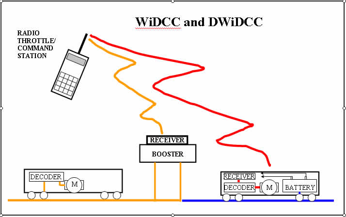
DWiDCC is not that much
different to a wireless throttle except that the command station smarts are
in the throttle and can be handled easily by one PIC with its DCC output
connected to the transmitting module. The receiver is connected to the input
of the booster (where the command station normally attaches) and the track
and loco decoder driven as in normal DCC.
Advantages:
- Option of running a normal DCC loco
in conjuction with DWiDCC locos.
- Easily installed into an existing DCC system
as all extras are "plug on"
Disadvantages:
- Receiver also needs to have a smart
interface between it and the booster that remembers current commands
and maintains the DCC signal on the track if communication is lost with
the handset.
- Dirty track is still a problem
DWiDCC enables track independent
control (and/or power) of a loco. The receiver is located within the loco
and its output is directly attached to the decoder.
Advantages:
- The decoder can be powered from
a battery, DCC track power or a nominal DC voltage applied to the
track (or all three)
- Booster not essential reducing electrical
complexity and cost
- Less hardware (power supply and control
signal conditioning) than existing decoders
- Track electrical properties can now be made
irrelevant
Disadvantages:
- Decoder has to be modified or manufacturers
lobbied to allow easy isolation of control input from power supply and
track
- Radio interference now a possibility but at
least trains don't drop out of the sky when this happens (my father builds
and destroys radio controlled planes on a regular basis:) and decoders
can be programmed to handle loss of carrier >
- A multiple handset protocol has to be established
if more than one handset is to be used
Experiment 1 - DWiDCC
In this experiment an existing DCC Command
Station designed by Robert Côté was
modified to fit in a smaller case, powered by batteries, and drive a 433MHz
transmitter module. An old Lenz LH100 decoder mounted on a HO chassis with
a sound module and headlamp was modified to take its command signal from
a 433MHz receiver module. Note that the receiver, decoder and sound module
would fit on a properly designed PCB in a mid to large HO locomotive. I will
have no problems fitting it into little 1:24 logging locos. The design is
very simple and yet - it works!
Materials
Parts for 1 x MiniDCC© system by Robert Côté
http://www.minidcc.com/
1 x Plastic Case 150x80x30mm - Jaycar HB-6034
1 x 433MHz Wireless Transmitter Module - Jaycar ZW-3100 $A9.95
1 x 433MHz Wireless Receiver Module - Jaycar ZW-3102 $A9.95
4 x AAA NiMH rechargeable batteries and flat holder
1 x 78L05 Voltage Regulator IC
1 x Red LED
1 x Yellow LED
1 x Diode
1 x 470R Resistor (Yellow,Violet,Brown)
1 x 2K2 Resistor (Red, Red, Red)
1 x 3K3 Resistor (Orange, Orange, Red)
 Left: The test setup
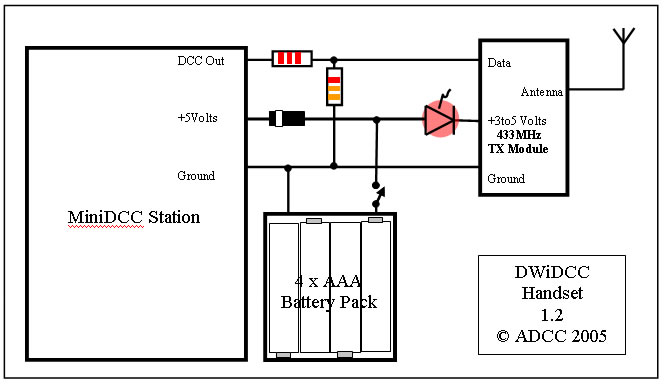
Circuit Diagram of Transmitting Handset
Construction
of Handset
The protype MiniDCC based handset was built on eurocard
with all components either soldered or plugged into this board. With
no loose wires the final PCB will make construction a breeze. The extra components
for DWiDCC are the battery holder, a diode to drop the battery voltage
to a suitable level for the PIC and a LED to indicate handset and transmitter
power which also drops voltage to near the 3 Volts required by the transmitter.
The DCC signal is reduced to 3V maximum by a resistor divider before entering
the transmitter module.
Here is a front view of the circuit assembly
Here is a rear view of the circuit assembly
Here is a left view of the circuit bassembly
Here is a right view of the circuit assembly
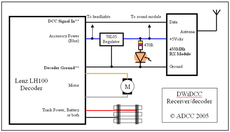
Circuit Diagram of Receiver and Decoder in Locomotive
Construction of Locomotive Receiver-decoder
Again the prototype was built on Eurocard. A long thin strip was used as a
base with the Receiver and its power supply soldered in. The decoder and sound
module were stuck on with double sided tape and connected with their standard
flying leads. A LED was added to notify the tester that the loco has track
power. The board contructon is as simple as the handset but there is one complication...
**Modifying the DCC decoder
For the initial experiment on a HO diesel chassis I
used an early Lenz decoder LH100 because I had one lying around and I have
a circuit for it that was provided to DCC WG members in the early 1990s by
Lenz. The relevant parts of a typical decoder are shown below:
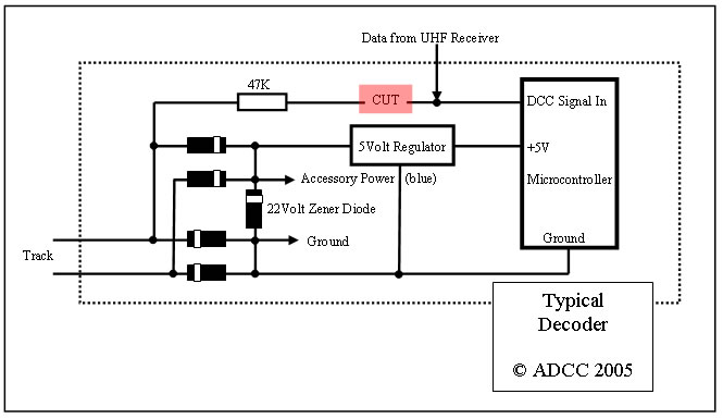
The track power is full wave rectified by the four diodes and the resultant
DC voltage limited to 22Volts by the zener diode. At the positive end of the
zener diode the standard decoder accessory wire (blue) is usually attached.
It is this line that is regulated to 5Volts to power the receiver. For test
purposes the negative end of the zener diode , which is the decoder ground,
had a wire soldered to it to provide a ground for the receiver. If you are
willing to keep poking around your decoder with a soldering iron you could
probably find the output of the decoders 5 Volt regulator and use it to power
the receiver.
Now comes the tricky part. The DCC signal line has to be traced from a track
wire via a resistor to the microcontroller. This line has to be isolated at
the microcontroller end. This end is where the receivers data output, the DCC
signal, is connected.
For my 1:24 Fairymead Mill 4wD loco I used a Digitrax
decoder. On examinination it was found to be similar to the Lenz decoder
and in fact easier to find a suitable point to cut by drilling out a via
on the printed circuit.
I have a circuit for the MERG decoder and although it is a bit more complex
(they have added a Schmidt Trigger to the line) it is very similar in design.
Afterall each manufacturers decoder has to perform in a similar fashion. That's
the beauty of standards!
If you are brave enough to poke around in another brand decoder I would like
to hear from you
Of course in the long term it would be nice if the manufacturers provide an
"External DCC Data In" option - just think of the extra sales and the step
in the door to the future of DCC.
This information is provided for
individual use only. Commercial production of this design may
only be undertaken under licence from ADCC.
© ADCC 2005
14/09/05, 29/04/06