Turntable Indexer (TTINDEX)
An optically controlled low component count turntable indexer
copyright Bob Backway 2000
Introduction
When it came to building my first turntable I found that most of the articles I had read on the subject involved bulky and less than precise mechanics and rather complex automatic control circuitry. In fact one article even went as far as using a micro controller!
My early experiments also used micro switches and were frustrated by the fact that these switches have to be set up in two planes and vary in sensitivity on a daily basis due to temperature changes. The notch that operated the switches was either too large to give reliable alignment or too small to reliably operate the switch. I had some optical swithes that I'd recovered some years back from PC 5 1/4" disk drives and these were so easy to set up and have remained in position for some years.
My original control circuit used flip flops to handle the set and resetting operations. On looking at this circuit after five years (a fellow modeller had made an enquiry) I started to do some "japanese engineering" and simplified the circuit further. Then it occurred to me that latching relays, more common and cheaper these days, could replace the flip flops and their driver transistors completely. The result is a circuit with minimal electronics - a beginners Veroboard project.
This circuit is provided for individual use only. Commercial production of this circuit may only be undertaken under licence from ADCC.
Parts List
1 Optical detector per turntable road (Jaycar ZD1901)
2 x Latching Relays (Jaycar SY 4060)
2 x 16 pin solder IC socket
2 x BC548 Transistors
2 x 1N4148 small signal diodes
1 x Double pole, double throw, centre off, momentry, miniature Toggle Switch (Jaycar ST 0512)
1 x 12 position Rotary Switch (Jaycar SR 1210)
1 x 47K resistor (yellow, purple, orange)
1 x 1K resistor (brown, black, red)
1 x 470 ohm resistor (yellow, purple, brown)
1 x 12 Volt power source
1 x Piece of 0.1" spacing veroboard
2 x 3 terminal PCB mounting terminal block
1 x 25pin male "D" connector
1 x 25pin female "D" connector
A few bits of insulated and uninsulated wire
Construction
I used a real vinyl record turntable (you may remember using them) as they are easy to pick up these days. They have good bearings, normally have a smooth, round outer edge which is easily driven by a quiet rubber wheel drive. This edge can easily be cut vertically with a thin hacksaw blade to provide the optical trigger path. I mounted the old turntable below the floor of the model turntable's pit with the centre shaft protruding to support the bridge. Another sheet of MDF was mounted under the turntable to hold the optical switches on their adjustable brackets. One switch is mounted beneath each road.
Until a PCB is available the Veroboard layout below will be found satisfactory. Take care drilling out the copper tracks under the board as marked by the red crosses. It pays for beginners to mount and solder one component at a time counting holes as a grid reference to component location. If you make a location mistake use Soderwick to soak up the solder and make for easy removal. I use a socket for IC's and normally place these first, then the lower profile components such as resistors and progressively work up to the larger components. This allows access into small spaces and places less stress on the larger components.
The Veroboard layout has the track cuts shown with a "X". Also shown are three "__" indicating the simple solder bridge method of connecting adjacent tracks on the underside of the board. The transistors are transparent so that their lead positions are clearer.
Click here for the Veroboard layout
The Road Select rotary switch and its connections to the optical detectors on the turntable are now wired. First remove the "stop" pin to allow continuous rotation. This switch has 12 positions, however for my six road turntable I used every second one. The positions used will depend on your layout and how you display it on the control panel. I added 25pin "D" connectors at the control panel and at the turntable with a flat ribbon running between them under the layout. A hand wired lead is just as good.
It is best to make and set up the turntable first with only one road in. To set up you rotate the turntable 180 degrees and shift the track (both ends, ie a parallel move)to half the necessary alignment. Then mark the other road angles on the detector mounting base and mount the detectors. Run the turntable to each new road and lay the track so the ends align. Try running to the road from either direction and again halve the error which is normally so small with this method that a light file on the inside of each track will ensure trouble free running.
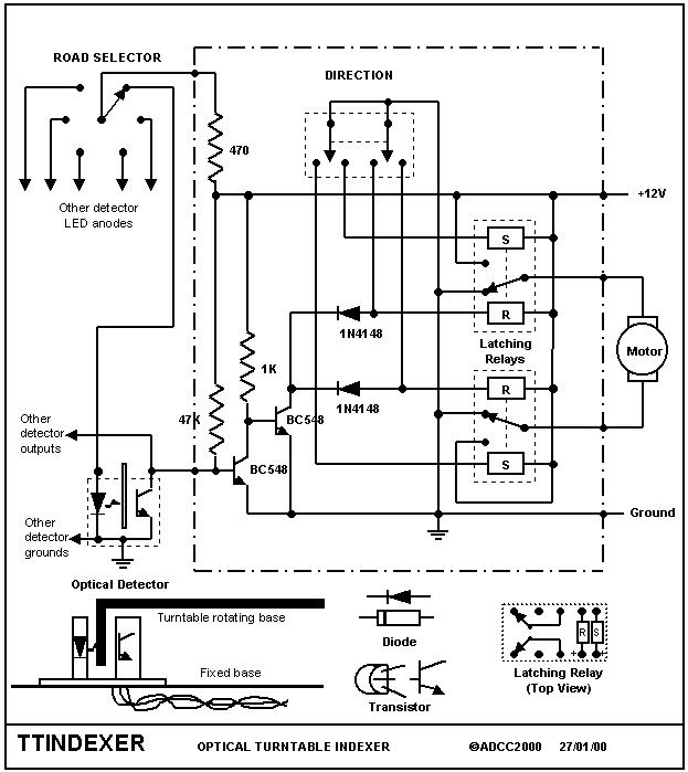
Jaycar Photo Interrupter
This detector has lead markings on the top of the unit. A diode symbol clearly shows the LED orientation and a dot marks the collector of the phototransistor. In order to wire this detector the pin at the emitter end (no dot) is bent and soldered to the pin at the bar end of the diode symbol. This is where the common ground wire is connected. The dot marks the detector output pin, again a common wiring point and the non bar end of the diode is wired to the road switch position for that detector's road. It would be best if these detectors were mounted on spacers to reduce stress on the pins.
Testing
Connect the motor* and apply power to the board. Push the direction toggle to the right and release it. The motor/tuntable should move round in a clockwise direction. If it rotates in the wrong direction swap the motor leads. Push the toggle to the left. The motor/turntable should now move in an anti-clockwise direction. Ground the detector output common where it enters the board at the base of the first transistor. The motor should stop. Set the other direction off and ground as before to reset the other direction. If the circuit passes these tests you can now connect the optical switches and start calibrating them.
*For bench testing purposes use a 1K ohm resistor and a bidirectional LED as a substitute for the motor. The colour red or green indicating power and direction. You may even want this little gimmick permanently mounted in your control panel.
The unit cannot detect if the turntable "flies" around. Mine takes 90 seconds to go through 360 degrees (no fast clock on my layout), but around 30 seconds should work. Use series globes, resistors or back to back diodes to reduce motor voltage and thus slow it down.
Circuit Description
Latching relays are quite useful for model rail projects. Unlike normal relays they remain operated when power is released and will not resume their original position until power is applied to the other, release, or reset coil. Thus they are an electromechanical equivalent of a flip flop. In the cicuit the relays are shown as single pole. They are actually double pole with both poles connected in parallel.
The direction setting switch sets one latching relay and resets the other thus starting the motor in the chosen direction.
The road selector switch applies power to the LED in one detector at a time - the detector for the chosen road. When the turntable has rotated to that road the light will pass through the hacksawed slit and cause the output of the detector to be switched to ground. The BC548 transistors amplify this signal and use it to reset the latches via isolating diodes. These diodes allow the detector to reset both latches while the direction switch can only set one and reset the other.
The motor is stopped by grounding both leads which should, in theory, hasten the halt.
Click Here if you have problems building this circuit
Back to general articles Menu
Back to ADCC home page
© ADCC 2000
28/01/00