USING DIGITAL SOUND MODULES
copyright Bob Backway 1997
Back to DCC Articles Menu
Back to ADCC home page
Unfortunately the Hallmark sound modules are no longer available. Would you believe Hallmark dumped their remaining stocks rather than ring those who had previously ordered them. As far as a greeting card they were a dismal failure for Hallmark.
Don't panic. You can purchase many different versions of recording modules as 15 second "note takers" "talking pictures" etc. Try the gadget section of a supermarket. I bought my last lot from Coles about a year ago. Tandy(Radio Shack) also stock similar units but at a higher price. My notes are just as useful with most of the recorders I've seen. You'll have to reverse engineer the circuit to find the vital connection points.
SOME ELECTRICAL SKILLS ARE REQUIRED...
Before you start installation of this unit ask yourself if you are capable of doing the job. As a modeller you should already be accustomed to performing fine work in constrained spaces. If this is true the fine soldering work should be easily accomplished providing you have the correct tools. A fine tipped reasonable quality soldering iron is required as well as a pair of instrument pliers and side cutters. If you haven't fine soldered before don't practice on this module, get an experienced person to help you. Beyond the initial test described in the quick start section we cannot be held responsible for any damage to the modules caused by incorrect installation.
Always work on the modules with the batteries or alternative power source disconnected!
TEST IT BEFORE YOU GO ANY FURTHER!
If the module has been pre-recorded:
- Remove the plastic tab marked "pull" from
the side of the module.
- Press and release the white button and you will
hear the recording.
-
To record a new sound:
- Remember that whatever mess you may make of your
recording it is not permanent, you may re-record as many times as you like.
- Move the red slide switch to the record position.
- Point the modules microphone at the sound source.
- Press and release the white button when you want
recording to start.
- Even if the sound has finished keep quiet and
don't move for the rest of the ten second recording period.
- Return the slide switch to the play position
- To hear the recording just press and release the
white button
-
If the recording is not what you expected try again, you may need to adjust the volume of your sound source or the distance you have the microphone from it. Once you have the sound as you wanted it is there permanently even if you remove the batteries.
POSSIBLE USES FOR YOUR SOUND MODULE
On board locos these modules can be used for bells, whistles, horn, chuff and the myriad of other less commonly available sounds associated with steam or diesel. The sound can be triggered using track magnets, timers and Digital Command Control functions.
In rolling stock the module could be any of your railway staff, boisterous passengers or distressed cattle, even the sound of heavy wagons coupling.
Around the layout your trackside machinery sound as real as it looks. Your cities can bustle with life, rural areas can be made spacious with distant sounds. Two modules recorded as a stereo pair can make thunder roll across the backdrop. These sounds can be triggered by passing locos, control panel buttons, timers and sequencers.
RECORDING TECHNIQUES
Direct miking
The sound module is shipped in a
form designed to make basic microphone recordings. Simply adjust the distance
from the source speaker and the volume of the source to obtain the desired
effect. Having the microphone too close to the source or the source volume too
high will cause distortion of the recording.
Line recording from hifi/video equipment
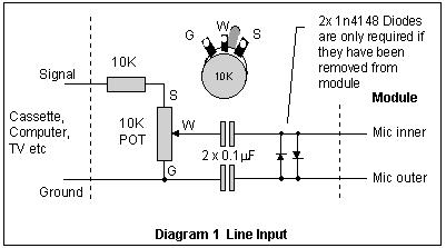 This method is much more controllable than direct miking. Simply adjust the level control to give the best recording. It is easier to make a copy of the original recording (the source may be another tape recording or video etc) onto tape and then carefully erase all sound from the tape before and after your sample. Thus if your sound is less than the 10 seconds of the recording you will not get the unwanted material following your sound.
If your unit has tone controls or a graphic equaliser use these to enhance your sample as you record it. For example as most applications require a small speaker the low frequency sounds require boosting with the bass control. An equaliser can also be used to enhance the sound above any background noises that may have been present in the original recording.
Using PC ".WAV" files
A personal computer such as a multimedia PC is the perfect tool for sampling and editing your sample files. The "Sound Recorder" utility in WindowsÔ
can edit your sample to remove any unwanted sound at the beginning and end of your sample. It can add effects such as echo and can replay at the press of a button.
To record directly from the speaker or line output of your sound card use the same interface circuit as shown for line recording.
Australian Digital Command Control has software and
hardware available that automates the recording operation by triggering the
sound module a preset time before outputting the sound to the module. On board
re-recording (see below) is also possible with this product.
A library of ".WAV" sound files is being compiled as part of the support for this product.
Re-recording after installation
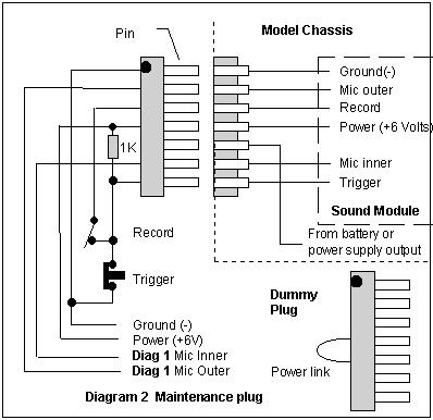 Should space allow diagram 2 shows a connector that can be provided to enable maintenance of the unit after installation. The connector is a standard 0.1" spacing made by cutting a round pin solder IC socket. A dummy plug connects pins 4 & 5, the local power, for normal operation. Pins have been allocated so that if the connection is reversed no harm can be done. The line inputs are connected to the outputs in diagram 1.
POWERING THE MODULES
Separating the battery pack for use in your model
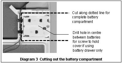 The battery pack can be carefully cut from the shipping module as shown in diagram 3 to create a separate battery pack. Alternatively the battery pack can be unplugged from the shipping module and a lid screwed over the batteries, this will allow it to fit in most HO scale rolling stock widths.
Other battery packs capable of holding four 1.5 Volt batteries such
as AAA, AA, C or D cells or even a lantern battery (G Scale!) may be used.
Obtaining power from a Digital Command Control signal
 This section shows how to power a module that is to be triggered by something other than the DCC receiver. For example obtaining power for a cattle van module to be triggered by a momentum switch. If the module is to be triggered by the DCC receiver a combined power and triggering circuit is shown in the Triggering section.
Digital Command Control has square wave signal alternating between plus and minus full DC voltage. This voltage requires regulation to 5 Volts for the sound module as shown in diagram 4.
Power supply for pulse
controllers and carrier command control
A pulse controller normally has a narrow pulse of full DC voltage even when a loco is stationary. Carrier command control normally has a full DC voltage on the track at all times. Increasing C3 to 100m
F in diagram 4 will provide a power supply for these types of control.
For reliable triggering with carrier command control the ground connection of the power supply must be connected to the ground of the trigger source, that is the receiver.
This power supply will also work for conventional DC control when the loco is travelling at a speed that has greater than six volts on the track. Thus this circuit is not suitable for conventional DC shunting, in which case a battery is the only alternative.
SPEAKERS AND OUTPUT DEVICES
Using different speakers
A search of electronic shops will provide a selection of small speakers(See section on getting bits). Two dollar shops are a good source of cheap headphones and kids toys that contain miniature speakers. Computer modem cards have the smallest speakers we have seen and can be obtained from broken units at computer swap meets. The only requirement is that the speaker have an impedance greater than 16W
(Ohms) which most of them have.
Trimming speakers
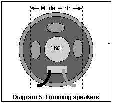 Speakers can be carefully trimmed with a sharp blade as shown in diagram 5. Provided the cut edges are not touching anything the sound is still quite reasonable. If you do find that a resonant note has been created try using a graphic equaliser to notch out the offending frequency.
Baffles and muffles
Speakers always sound better if baffled as air cannot "leak" from one side to the other. Even gluing a speaker to thick card or the floor of the rolling stock with a hole for the sound to exit improves the quality of sound dramatically. Often a layer of thin foam rubber over a speaker can remove the harsh high frequencies and mellow the sound.
One speaker for two modules
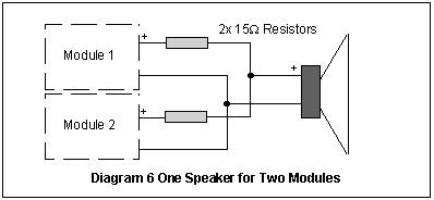 Two sound modules can be used with one speaker in a constricted area as shown below. The resistors isolate the speaker outputs of each module so that they are not destroyed by each other.
Getting more volume
with a power amp
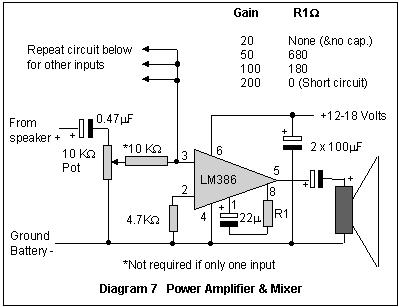 Some say sound should be scaled, there is nothing worse than hearing a layouts ding dong gates at the other end of the hall! However if you desire more volume try the amplifier shown below in diagram 7.
Multiple modules into one power amp
Several modules outputs may be mixed and their levels individually set using the mixer circuit shown added to the amplifier in diagram 7. The circuit is repeated for each input connected to pin 3 of the LM386.
TRIGGERING THE MODULES
How the module triggers
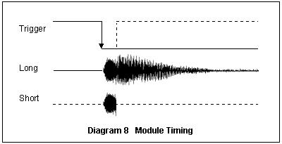 The timing diagram below shows how the voltage applied to the trigger lead controls recording and playback. The unit is triggered on a transition from full voltage to no voltage (ground) and the sound continues to play as long as the trigger remains grounded. Removing the trigger stops the sound as shown by the dotted line. This can be useful with, for example, short and long whistles. As shipped the module is triggered when the white button is released and allows the whole sample to play.
Digital or Carrier Command Control function
(accessory) outputs
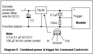 Command control decoders having function/accessory outputs can normally be directly connected to the sound modules. Check with your supplier that the outputs are "active low". The current drawn by the module is well under 100mA and should not effect the decoder. The combined power and trigger circuit shown in diagram 9. The components can be easily fitted to the existing circuit board. Solder in order - 10K resistor, 0.1 capacitor, the voltage regulator with its input free and C3 between "-" and this free end.
Computers
As with command control accessory output a computer interface is normally designed to be "open collector" either using transistors, opto couplers or relays. The same circuit in diagram 9 can be used.
Light
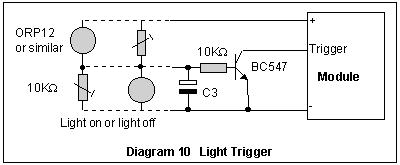 In diagram 10 a photocell is used to turn a transistor on when interrupted. The transistor (just about any NPN type) triggers the sound module. A control over light sensitivity is provided and the trigger can be extended using the capacitor. Swap the sensitivity adjustment pot with the photocell to reverse the activation from light off to light on.
Momentum
Suspended Weight
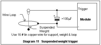 The circuit in diagram 11
shows how a suspended weight can be used to trigger the module. The capacitor keeps the module triggered if the weight touches the loop for less than the sample period, adjust it to suit. This circuit has been used to make the cattle complain when the truck rocks!
The circuit in diagram 11
shows how a suspended weight can be used to trigger the module. The capacitor keeps the module triggered if the weight touches the loop for less than the sample period, adjust it to suit. This circuit has been used to make the cattle complain when the truck rocks!
Mercury Switch
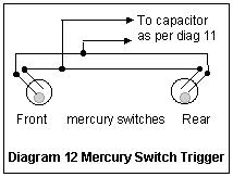 A mercury switch adjusted to the right angle as per diagram 12 can be used to trigger a crunch sound when a piece of rolling stock couples. The best way to make the switches adjustable is to solder them to 16# wire that can be bent to a suitable angle. With two switches the circuit will trigger in either direction.
Reed Switch
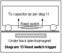 A reed switch is about the simplest way a sound can be triggered on a moving train that runs on conventional DC or pulse controller. The circuit in diagram 13 shows you how to do this. The circuit triggers every time the carriage passes over the magnet, the length of which is a factor in the play time. An electromagnet will only trigger when switched on.
Reflection
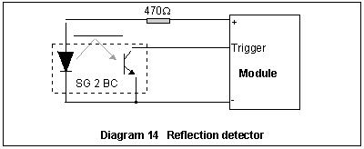 Reflection detectors are ideal for "chuff" generators. The inside of a loco driving wheel is segmented into four with black paint. The segments are painted silver if the wheels are not reflective enough and the reflection detector is mounted under the chassis. Refer to diagram 14.
Sequencers
Sequencers can be bought or made, they have similar outputs to the other controllers mentioned previously. The electronics hobby press has published designs from time to time.
Track Detectors & Accessory Decoders
Track detectors normally switch to ground and so can be placed between the trigger input and ground in common with the units battery "-". If you wish to use 12 volts to power the module use the circuit in diagram or use the combined power/trigger circuit of diagram 9.
Remote Switch
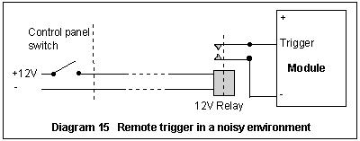 The trigger wires can be extended to a control panel. If a noisy environment causes false triggering use a relay to isolate the module.
;
Timers
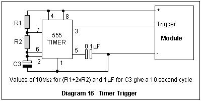 A simple timer can trigger the module at regular intervals. Unless you are simulating a piece of machinery be careful with this one as the effect can be unrealistic and tiring. Try various values for the timing components to get the effect you want.
Axel Cams
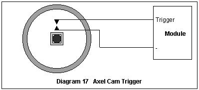 A square cam on a driver axle, or two "bumps" on a pony or tender axel of approximately half the drivers diameter, can trigger the module for use as a chuffer. One "bump" can give a tram a flat wheel! See diagram 17.
FITTING THE UNITS INTO TIGHT SPACES
Some components aren't needed for playback
Using the "Japanese approach" it was found that the capacitors C1 & C2 that mount off board do not appear to effect playback and so if space is a premium remove them. The record/playback slide switch can also be removed if playback only is required.
Trimming the board
The diodes D1 & D2 are also only used for recording. If you have first class soldering skills it is possible to reduce the board size to being not much larger than the black epoxy "blob". First draw a diagram of both side of the board showing connections and copper track layout. Pay attention to +6Volts, -Ground, 2 speaker wires and the trigger wire. Scrape the green solder resist off these tracks that require connection for playback as close as possible to the blob and reconnect them and test the board. If you have not destroyed the module so far carefully trim the module down to the smallest size possible that allows the connections to remain.
NOTES ON CONSTRUCTION
Try it off the model before committing yourself
At every opportunity carefully test the module during the installation process. The battery pack can be used for power if the model has not been powered as yet. Place the positive 6 Volts wire after the regulator if one is used. Connect 12Volts from your power pack (the right way round!) to check the module and the voltage regulator.
Try to make it serviceable
Consider that you may one day obtain a better sample, a real classic that would enhance your model even more. Try and make the module serviceable, give consideration to providing the re-recording connector.
Miniature construction techniques
Many of the circuits provided in this manual require a few extra components that require space. There are two options. The simplest is to solder the components onto the module';s printed circuit board. Another method is to solder a "birds nest", that is solder the components together as close as possible in a three dimensional sculpture. Extra circuit boards are a luxury which can often be done without in this hobby.
A search in the suppliers catalags can reveal the smallest components for the job. For example tantalum capacitors are smaller than electrolytics, DIP bridge rectifiers are available, trim pots (variable resistors) can be purchased in a 0.3" diameter three pin package. These smaller components are often only slightly dearer than the larger ones as they are used most often these days.
GETTING BITS
Below is a list of electronic component suppliers, many of which have a free or low cost catalogue which should be in any hobbyists library. Most also have mailorder facilities details being provided in their catalogues. Use your phone directory or purchase an electronics magazine to find your closest outlet. It pays to shop around, prices can vary by as much as 100%, some outlets have "got the lot" but you pay for their excellent wharehouse.
- Altronics
- Dick Smith Electronics
- Farnell Electronics
- Jaycar Electronics
- Radio Parts Group
- Radio Spares
- Tandy Electronics
- Your local electronics repair shop
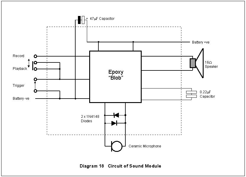
CIRCUIT DIAGRAM
Back to DCC Articles Menu
Back to ADCC home page