A Train Shuttle Throttle
copyright ADCC 1999
Introduction
This circuit was designed for a fellow NMRA member who wanted to automate the action of a gantry crane moving from one end of a yard to another along a dedicated track. This shuttle throttle will work in any similar application requiring a loco to move from one point to another and back again on a repetitive basis. Various detectors can be used at either end, the simplest being reed switches operated by concealed magnets on the loco/crane. Accelleration, maximum speed,decelleration and stop wait time are independently adjustable. Run, east and west indicators help debugging track wiring and provision is made for an emergency stop switch. An accessory control output is provided to operate related devices such as signals or unloading operations.
Parts List
1 x 14013 Dual CMOS Flip-flop
1 x 14093 Quad CMOS Schmidt Nand
1 x LM324 Quad Op Amp
1 x LM317 Voltage regulator
1 x LM78L12 12 Volt Voltage regulator
1 x NPN General Purpose Transistor
1 x 2A Bridge rectifier
2 x 1N5401 Power diodes
5 x 1N4148 Small signal Diodes
1 x Green LED
2 x Orange LEDS
1 x 1M Pot (pots can be trim pots or PCB mounting knob pots)
2 x 50K Pots
1 x 2K Pot
1 x 1M0 Resistor
2 x 10K Resistor
3 x 1K2 Resistor
3 x 1K0 Resistor
1 x 220R Resistor
1 x 2200uF Electrolytic capacitor
2 x 33uF Tantulum Capacitor
5 x 0.1uF Capacitors
2 x Reed Switches
1 x Small Magnet
2 x 4 Terminal PCB Terminal Block
1 x Double Pole, Double Throw 12Volt PCB mounting Relay
1 x Single Pole, Single Throw Emergency Brake Switch
Circuit Description
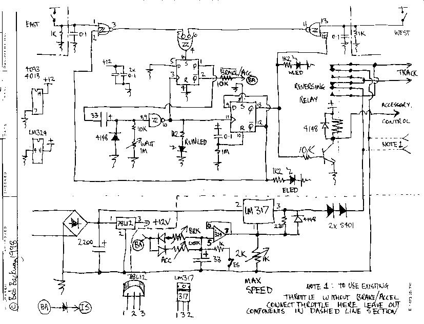
The circuit can be divided into two parts, the throttle section and the east-west control section. The throttle section uses an LM317 voltage regulator the DC output of which is controlled by the voltage present at pin 1. The maximum voltage is set by a 1K0 pot but can be reduced by the LM 324 op amp voltage follower connected across it. The voltage output by the LM324 is determined by the voltage across the 33uF capacitor. This voltage rises during accelleration when a voltage near the supply voltage is applied via the accelleration rate pot from the east-west control circuit. When braking is to be applied the control circuit applies a voltage near ground to the same point allowing the braking pot to discharge the capacitor. The diodes at the junction of the pots ensure the correct pot influences the capacitor voltage at the appropriate time. In fact if a 10K pot is connected between supply and ground and it's wiper is connected to the control point you have a simple throttle with momentum and braking.The two high current 2A diodes on the output of the LM317 allow the minimum voltage to drop low enough to stop the loco.
The east-west control circuit consists of two flip-flops, one to control accelleration and braking, the other direction of travel. The east and west detection reed switches are buffered and enabled by 14093 CMOS schmidt trigger nand gates. The appropriate reed setting the brake flip flop when closed. The brake flip-flop reduces the voltage output of the throttle via the brake pot as previously described. This causes the loco to eventually stop. Thus the reeds have to placed the braking distance from the desired stopping point. The braking flip-flop also starts a simple nand schmidt trigger timing circuit, the delay of which is set by the "wait" pot. The delay starts from the start of braking and ends by clocking both flip-flops. The braking flip-flop now releases and accellerates the throttle via the accelleration pot. The reversing flip-flop toggles direction, operating the relay thus causing the loco to return, accellerating past the disabled reed at the starting end, travelling at maximum set speed and eventually triggering the reed at the other end and start the cycle again.
Controls included are Brake, Wait, Accelleration and Maximum speed. An optional Emergency stop switch is included. Indicators provide direction (East or West) and Running. The circuit can also control accessories such as signals, gates and trigger loading operations.
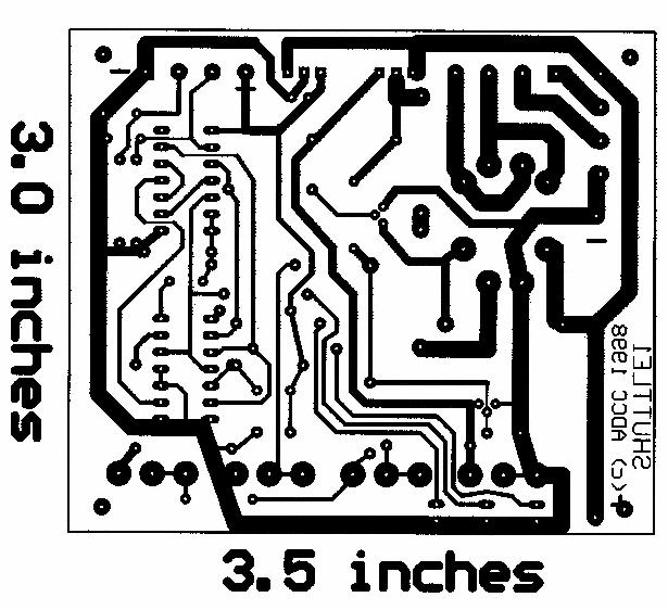
Print and then shrink to dimensions shown onto transparency film using a photocopier.
Back to Non DCC Articles Menu©ADCC1999
20/07/99