Low component low or high wattage Lighthouse beam simulator with automatic dark-on, or manual control
copyright Bob Backway 2000
| Introduction
The traditional lighthouse has a rotating beam which would require a considerable amount of mechanics to reproduce in a model. Circuits to simulate a rotating beam with a stationary globe have appeared from time to time. They use a triangular wave and threshold adjustment to slowly bring the light on and off to simulate the beam moving into, and out of the observers view. This circuit (and I admit the icing on the cake was a fluke) smooths the triangular waveform to provide a mathematical "Bell Curve", again adjustable, to give a more realistic beam movement than a triangular waveform. This circuit is provided for individual use only. Commercial production of this circuit may only be undertaken under licence from ADCC. |
 |
Parts List
1 Piece of Veroboard 2.4" (24 holes) wide and 2.3" (23
holes long)
1 x 4 way PCB mounting terminal block
1 x Single pole, double throw, centre off, miniature Toggle Switch (Jaycar ST 0558 or ST-0560)
1 x 12Volt globe 3 to 5 Watts (eg instrument panel globe)
1 x MTP3055 MOSFET
1 x 7555 Timer Integrated Circuit
1 x 8 pin PCB mounting socket
1 x LDR (Light Dependent Resistor) Jaycar RD-3480 or similar
2 x 3mm LED's colour of your choice
1 x 100K miniature trimpot
1 x 1M0 resistor (brown,black,green)
1 x 680K resistor (blue,slate,yellow)
1 x 330K resistor (orange, orange, yellow)
2 x 220K resistor (red, red, yellow)
1 x 4K7 resistor (yellow, purple, red)
2 x 1K0 resistor (brown, black, red)
1 x 33microfarad 16VW tantalum capacitor
1 x 1microfarad 16VW tantalum capacitor
1 x 0.1 ceramic capacitor (not shown on circuit - see notes)
1 x 0.01 ceramic capacitor
Links from cut off component leads
Construction
Until a PCB is available the Veroboard layout below will be found satisfactory. Take care drilling out the copper tracks under the board as marked by the red crosses. It pays for beginners to mount and solder one component at a time counting holes as a grid reference to component location. If you make a location mistake use Soderwick to soak up the solder and make for easy removal. I use a socket for IC's and normally place these first, then the lower profile components such as resistors and progressively work up to the larger components. This allows access into small spaces and places less stress on the larger components.The Veroboard layout has the track cuts shown with a "X". Simple wire links are shown as "__". Also shown at pin 1 of the timer as "__" is the simple solder bridge method of connecting adjacent tracks on the underside of the board. Tricky components are shown in detail on the circuit diagram and with extra lead markings on the Veroboard layout.
Click here for the Veroboard layout
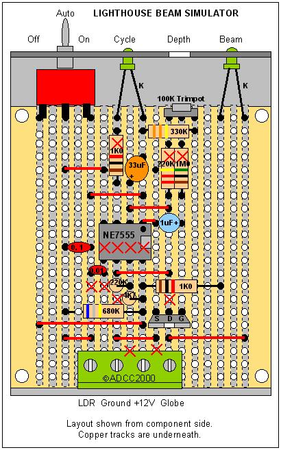
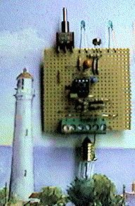
Click here for a view of the board
Testing
Apply power to the unit with the auto/manual
switch in the "On" position .
The "Cycle" LED should light for approximately 6 seconds and be dark for the
same time. With the adjustment trimpot wound up fully the beam should light
after the cycle light does and extinguish after the cycle light extinguishes.
Adjust the trimpot so that the "beam" gently lights to full strength, stays
there for a small time to represent beam width and then gently fades.
Now try the auto mode by switching the toggle switch to the centre position. Experiment with a desklamp and your finger to apply light and dark to the LDR and so stop and start the timer. Be sure to seperate the LDR from the lamp with a screen or unexpected results may occur!
Circuit Description
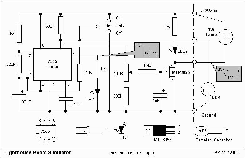
Click here to see the waveform produced
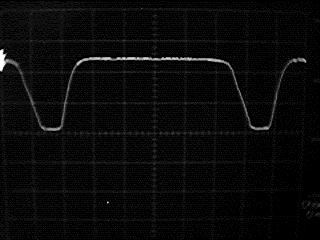
The basic rotational interval is created by the industry workhorse 7555 timer integrated circuit. A 47K and 220K resistor with a 33 microfarad capacitor set the time interval at around 12 seconds. This is faster than a real light but appears more real in the model. The output of the timer, at pin 3, flashes the optional timer LED to indicate its successful operation.
A triangular waveform that moves between 1/3 and 2/3 of the power supply voltage
appears on pins 2 and 6 of the timer and is used internally to "flip" the
timer. This waveform is connected to a trim pot which sets the threshold
for applying voltage to the 1M resistor and 1uF capacitor smoothing circuit
attached to the gate of the MOSFET. The smooth waveform applied to the high
impedance gate of the MOSFET is amplified to control the lamp.
The 7555 pin 4 is a reset pin. Switching this pin to +12Volts turns the beam
timer on, grounding this pin turns it off. In the centre position the toggle
switch allows the reset pin to be controlled by the LDR and a 680K resistor.
When dark the LDR is high resistance enabling the timer. When enough light lands
on the LDR it goes low resistance, shorting the reset pin to ground thus stopping
the timer. A 0.1uF capacitor (not shown on the circuit diagram) is connected
from pin 4 to ground (and thus across the LDR) to smooth the day-night transition,
prevent electrical noise from resetting the timer if the LDR is on a long lead
and remove accidental shadow effects.
The unit drives a 3 to 5 Watt lamp without the need of a heatsink on the MOSFET.
However if the MOSFET is mounted on a suitable heatsink via insulating washers
its 12Amp capacity could be used to drive 100Watt globes!
Click Here if you have problems building this circuit
Back to general articles Menu
Back to ADCC home page
© ADCC 2000
30/11/00 - Last Updated 02/12/05