The HTML/Javascript code is at controller client html (Turn the ignition on (top left button) to begin operation! )
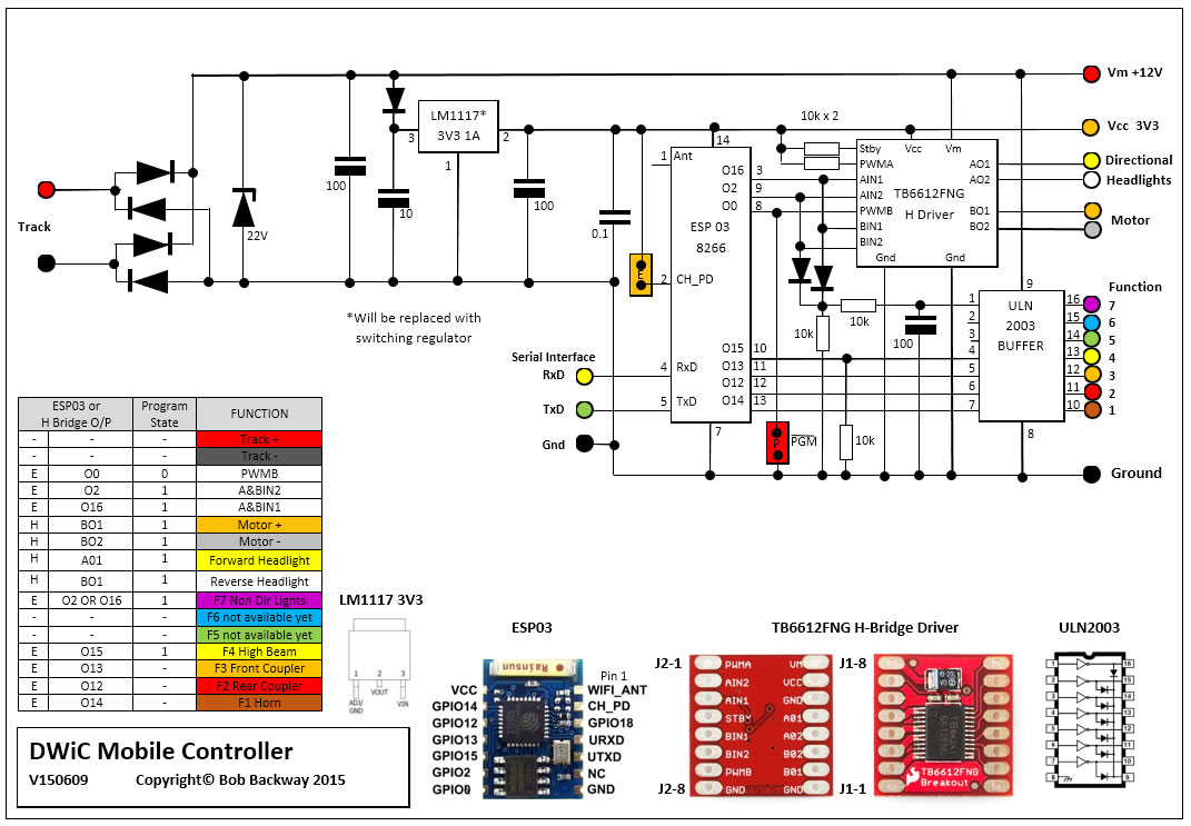
Circuit Diagram:
Below is an earlier version of the board layout just to give you an idea of how it looks. Note a surface mount design would be much smaller (similar to a DCC decoder).
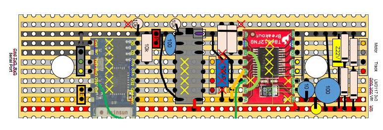
Note how some of the ULN2003 pins are bent up to allow tracks to pass under between the ESP03 and the H-Bridge driver.

Binary files:
To quickly load binaries onto an ESP module you use Flasher(Win32) or Flasher(Win64) and a USB-serial interface such as this one from Worldchips. Connect Gnd to Gnd, Tx to Rx and Rx to Tx. Separately power board as the USB-serial interface can often not supply the current required.
To program controller:
1. Power controller
2. Run Flasher.exe.
In "Advanced" window of Flasher.exe check baud rate is 9600. Enter files into the "Config" window of Flasher.exe in the following order...
| File | Location |
|---|---|
| blank.bin | 0x7E000 |
| esp_init_data_default.bin | 0x7C000 |
| 0x00000.bin | 0x00000 |
| 0x40000.bin | 0x40000 |
| webpages.espfs | 0x12000 |
On completion of programming:
1. Remove enable jumper and then programming jumper
2. Replace enable jumper
3. Check WiFi working with phone or tablet
4. Enter IP address 192.168.4.1 into browser
5. Run train