This is the first of several articles intended to explain the technology behind Digital Command Control in the hope that the average modeller may gain a greater understanding of how and why these standards and techniques were adopted. In this article the electrical specification or "what's on the track" will be compared with previous technologies, the advantages and disadvantages discussed and some block diagrams to show how the track signals are used and decoded.
Before we continue a few buzz words require
definition:
Binary
A method of counting with a base of two (we normally count with a base of ten in decimal). With binary each digit has only two states, "one" and "zero", so the binary number "1011" is equal to the decimal number 11. Reading from the right it has a one, plus a two, no fours and an eight in it. In mathematics format:
1x1+1x2+0x4+1x8=11
Cycle One complete positive voltage swing followed by a negative voltage swing of an
electronic signal.
Frequency The number of cycles per second, unit Hertz(Hz).
Half Cycle A cycle has two halves, the positive half cycle and the negative half cycle.
Microsecond One millionth of a second, a relay takes 20,000 microseconds to operate!
The difference between Analogue & Digital Command Control
We all know that a simple pure DC controller applies a DC voltage of between 0 Volts and a nominal 12 Volts to the track depending upon the speed setting. We also know that the direction the engine travels is determined by which polarity wire we attach to what track, the reversing switch just swaps the wires around to cause the loco to travel in the opposite direction.
With command control neither of these is true, the full voltage is always present and the loco's direction of travel is determined by the command controls it receives.
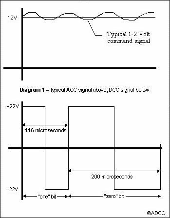
With Analogue Command Control [as defined by the NMRA] these command controls are typically transmitted to the loco by superimposing a control signal onto the DC track voltage. The control signal can be separated from the power signal by the loco's receiver which regulates the track voltage to the motor to an appropriate voltage for the speed command received. The command control signal is typically one to two volts. It cannot be greater than about one tenth of the power signal (12 Volts DC) or it will start to influence motor speed, particularly at low speeds. Thus it can be said that an ACC system will have a command signal to power signal ratio of around one to ten, more on this later.
Digital Command Control's first claim to fame is that the power and the command signal are one in the
same. The power signal is not a constant DC voltage but what is called a square
wave.
 The power signal changes polarity thousands of times a second in a similar way that your home’s electricity supply changes at fifty times a second. The cunning trick here is that each cycle, that is a positive plus a negative swing, provides one bit of data information of the command signal. This is done by ensuring that a bit that transmits a binary zero takes at least twice as long to complete a cycle as that for a binary one.
DCC has a power to signal ratio of one to one as these signals are one in the same. Electrically speaking a model railway is a very noisy environment with motor brushes, inductive pulses from motors, small breaks from track pickups and dirt on the track. This noise interferes with any command controls ability to get its command through to the loco's receiver particularly when you consider it is possible for noise spikes to be several times greater than the power signal.
Electrical noise is measured as the signal to noise ratio, the greater this ratio the less influence the noise will have on the CC system. With DCC having a power to signal ratio of 1:1 it provides the best signal to noise ratio you can get, given that the motor noise etc are the same in either system.
Specifying the DCC signal
Now that we know that DCC sends bits of information as binary ones and zeros using the width of a complete cycle we'll take a closer look at this waveform.
The frequency or bit duration limits for DCC are dictated by the requirement in some countries of a 10 KHz upper frequency over which more stringent radio interference regulations apply. When you think about it a model rail layout makes a nice big antenna!
Nominally each half cycle of a "1" bit must have a period of 58 microseconds giving a total time of 116 microseconds. To allow some design latitude a command station may transmit 1's with a period from 55 to 61 microseconds long and a receiver must accept as a "1" a half cycle from 52 to 64 microseconds long.
The "0" bits have a more complex specification
which allows another of DCC’s claims to fame. As previously mentioned each
half cycle of a "0" must be roughly twice that of a "1", at
least 100 microseconds. In addition to this one half cycle of a "0"
can be stretched to around one hundred times its minimum length. This is done to
provide a net DC offset to the signal to allow one conventional DC loco to run
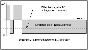
on the same track. If say the positive half cycle of a "0" is 100
microseconds long and the negative half cycle is 10000 microseconds the energy
total of the two half cycles (the area
 shaded in diagram 2) will cause a DC loco to move in reverse. The number of zero’s stretched in this way provides a cumulative effect and controls the speed at which the loco moves.
A command station can transmit zeros with each half cycle having a duration of between 95 and 9900 microseconds as long as the total cycle does not exceed 12000 microseconds. For a decoder the figures are 90 to 10000 microseconds, again to provide some design latitude.
How are the bits transmitted and received?
When reading any specification, figures and buzzwords can quickly confuse the issue. In practice the transmission and detection of a DCC signal is really quite simple.
A command station assembles the commands and transmits them. It knows whether it is sending a "1" or a "0" and what half cycle is currently being transmitted. The transmission system operates at the higher frequency of the ones. When a zero is being transmitted it simply skips a cycle, called dividing by two to make the pulse twice as long. To stretch zeros in order to run a conventional loco it just counts the zeros. With a top speed of fourteen and if the loco is on speed five, five out of every fourteen zeros are stretched by extending the appropriate half cycle by many cycles. The half cycle that is divided is the same for all those stretched and depends on the direction the operator has selected.
 But, you may say, with only the zeros stretched, how can the loco reach full speed?
The answer is that the DCC signal typically has a half cycle voltage of plus or minus 22 Volts peak, stretching only the zeros is sufficient to reach top speed.
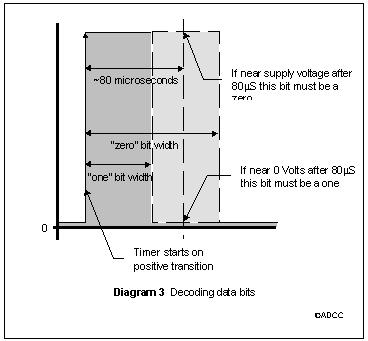
The way a decoder works out if the data bit it's receiving is a one or a zero is even simpler. One half cycle of the track signal is monitored by the system which waits for a transition between two half cycles (which half cycle doesn't matter as long as it only looks at the change in one direction) and starts counting or timing. After approximately 80 microseconds it checks the signal voltage, if it is near 0 Volts it has received a "1" if it is at the supply voltage it is a "0". Spend some time looking at diagram 3 before you ring me!
Signal Shape and Voltage
The standard specifies aspects of the signal shape that are beyond the scope of this article. Suffice it to say that the intention is to ensure the signal is clean enough to be detected, reduces radio interference and can allow the superimposition of certain other command control signals as long as they don't interfere with the DCC signal. On this last point systems have been designed with a combination of CTC and DCC and OnBoard Analogue and DCC. The Trix system and Zero1 have also been combined with DCC but I believe this has been done using an alternating signal arrangement, both systems being digitally based.
The RMS Voltage, defined as the equivalent DC voltage, of the DCC signal is not to exceed the nominal voltage for the particular scale plus 2 Volts. The extra voltage is to allow for the voltage drop across the power supply components of the decoder. The maximum voltage peak of the signal should not exceed +/- 22 Volts and should be greater than +/- 7 Volts. For voltages below 7 Volts some decoders may automatically go into programming mode.
If you are new to command control you may not have realised power supplies for mobile equipment are easily built for DCC controlled equipment. As full power is present on the track at all times a bridge rectifier converts the AC signal to a steady DC voltage and a cheap three terminal regulator reduces the voltage to the whatever your circuit requires. All manner of light, sound and animation effects can emerge from stationary loco.
The standard has a note warning of the effect the DCC signal may have on coreless motors. The DCC signal can damage coreless motors if the signal is directly applied to the loco. The reason being that they react to the high frequency component and can't dissipate heat as well as a conventional motor. This problem can occur with some pulse type controllers as well. Of course these locos can be run without any problems if equipped with those decoders already available that have been designed to control such motors. Ó
ADCC1995
Please refer to NMRA Standard S-9.1 for further information.
Back to DCC Articles Menu
Back to ADCC home page
 The power signal changes polarity thousands of times a second in a similar way that your home’s electricity supply changes at fifty times a second. The cunning trick here is that each cycle, that is a positive plus a negative swing, provides one bit of data information of the command signal. This is done by ensuring that a bit that transmits a binary zero takes at least twice as long to complete a cycle as that for a binary one.
 shaded in diagram 2) will cause a DC loco to move in reverse. The number of zero’s stretched in this way provides a cumulative effect and controls the speed at which the loco moves.
 But, you may say, with only the zeros stretched, how can the loco reach full speed?