More Realistic Lighting With DCC
copyright Bob Backway 1997
Back to DCC Articles Menu
Back to ADCC home page
The light and function outputs of a typical Digital Command Control decoder module allow a locomotive to display more prototypical lighting behaviour. In addition to the front and rear headlight outputs found in most decoders many have at least two function outputs. With four function outputs available horn, engine idle and uncoupling are also possible. With eight function outputs your imagination can run wild! This article demonstrates how a simple electrical circuit can utilise a limited number of functions to create a seemingly greater number of effects. As full power is always present with DCC these effects can happen whether the loco is stationary in the yard or at full throttle on the main.
Circuit Description
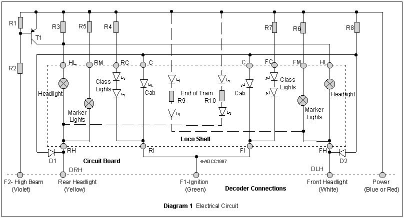
Looking at the circuit in Diagram 1 it can be seen that one function controls the cab and marker lights. This function, which I call "Ignition" (likened to the ignition switch in the loco cab), can also drive an "engine idle" sound the subject of a later article. When the ignition is switched on the class lights and cab lights come on and the loco bursts into life in the yard without having to move. It looks great.
There is nothing worse than a model loco roaring along the main at night with the cab lights on, how can the driver see through the windscreen? In this circuit the two diodes D1 & D2 fix this by "grounding" the power to the cab light LEDs when either headlight is on.
The second decoder function controls the high/low beam of whichever headlight is currently on by switching a resister in and out of the headlight circuit. When the High Beam function is on the transistor is on shorting the resistor and applying full power to the lamps. With the function off the lights a dimmed by the transistor going off switching the series resistor into the circuit. Now the loco can dim its headlights when approaching a station or waiting in a passing siding. This is called Rule 17 in the States and adds a new dimension to operating sessions.
In Diagram 1 the End of Train indicator wiring is drawn as dotted lines. Connected as shown the EOT's will be controlled by the locos direction of travel as done in most commercial models. If you have a four function decoder and are using the remaining two functions for the uncoupler described in my last construction article, these functions can also be used to drive End of Train red LEDs. When the uncoupler is operated the End of Train lights are activated also giving a good visual indication if uncoupling at the other end of the yard. The logic in using the uncouple functions being that if nothing can remain coupled to that end it must be the end of the train.
Parts List
Any DCC compatible Decoder with at least 2 function outputs.
Short length 1.5mm optical fibre12Volt grain of wheat globes
3mm Yellow(not amber) LEDs
Rectangular yellow(not amber) LEDs
Miniature red LEDs
1.1" x 0.8" piece of 0.1" Veroboard
T1 BC327 or similar 800mA PNP Transistor
D1, D2 1N4148 or similar Small Signal Diodes
R1, R2, R4, R7 4K7 Resistor
(Yellow, Purple, Red)
R9, R10 10K Resistor (Brown, Black, Orange)
R8 1K0 Resistor (Brown, Black, Red)
R5, R6 75R Resistor (Purple, Green, Black)
R3 56R Resistor (Green, Blue, Black)
Very Thin black wire, Aluminium foil, Masking tape, Double sided tape
Construction
I have found it best to assemble the whole lighting system on the bench first. This enables testing and light intensity adjustment away from a delicate model. The brightness of all LEDs & lamps may have to be adjusted to suit the particular brand that you purchase. Simply replace the appropriate resistor with the next higher value to reduce brightness or the next lower value to increase brightness. Once everything is OK and the optical fibre assemblies added the whole unit can be mounted and the wires routed clear of motors, windows etc and shortened at the PCB connection end.
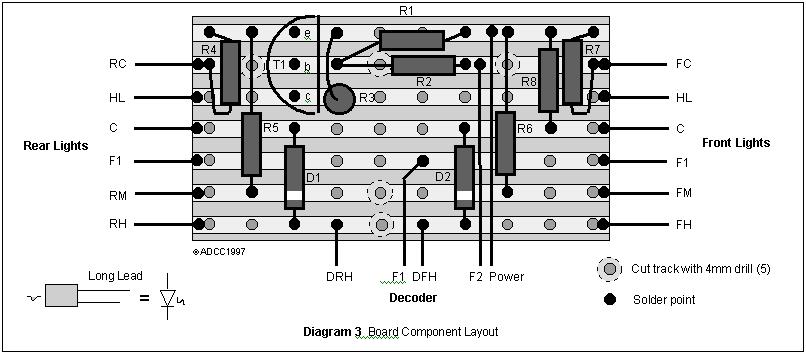
Assemble all the components on the copper track side of the printed circuit board, the opposite side to where they are normally mounted, as shown in Diagram 3. Pay particular attention to the diode orientation indicated by the diode's band. If the board can be mounted toward one end of the loco solder a cab LED directly to the board. Later the cab lights should be hidden out of view on the ceiling so as to fill the cab with a soft glow.
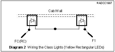
Check the fit of the rectangular class light LEDs in the class light holes. They can be filed to be a tight fit in the hole and flush with the outside surface so the class numbers can be glue on to them. Solder the long wire of one to the short wire of the other in series as per Diagram 2. It is important to have two LEDs both the same way round as they will only allow current flow in one direction. Trim the other ends short and solder lengths of wire to them
The class numbers were printed on laser printer transparency film using a Word processor capable of printing clear characters on a black background (for example Microsoft Word). One page of transparency film can contain an entire railroad of class numbers. Trim the film to fit the shape of the class light and glue in place. A black drawing pen was used to "draw" the rubber grommet around the class light.
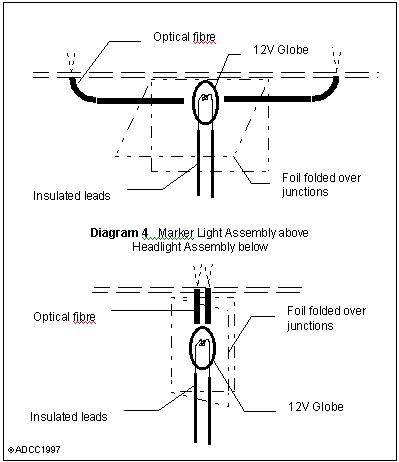
Next come the marker lights. Using Diagram 4 as a guide cut two short lengths of optical fibre. I bent the ends by pressing an end gently against the edge of my bench and held the soldering iron close to but not touching the end. The radiant heat will soften the polymer fibre and it bends under the pressure. Careful positioning of the iron will control the location and radius of the bend.
Once both fibres are bent and checked for fit, ensuring clearance for the globe, they can be formed into a "T" and a piece of aluminium foil wrapped around the three way junction. The foil has two tasks. Firstly it acts as a light seal ensuring all the available light can only go out through the fibres and secondly it acts as a heat sink for the globe. Place at least two layers of foil over the globe and make them as large as you can. I have seen a globe melt the end of the fibre! Finally use masking tape to hold the foil in place. Ditch lights, not shown in the circuit, can be made in the same way and wired to the same points as the class lights.The headlights are formed in much the same way either using one or two fibres, depending on your locos light pattern. Cut the fibre at least 10mm long to ensure the headlights have a realistic narrow beam that you can see along the track.
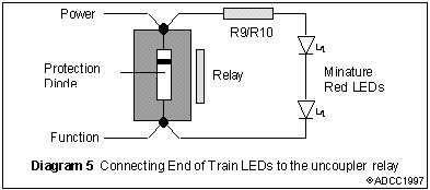 For the end of train lights I use miniature red LEDs. As with the class lights these are also soldered in series, but this time the resistor is soldered between them. Be sure to check the spacing. These are either soldered between power and the opposite end headlight or, more realistically, connected across the uncoupler relays if a four function decoder is available. If you connect them across the relays the diodes are connected in the reverse polarity (opposite way) to the protection diodes already installed as shown in Diagram 5.
Testing
Connect +12 Volts from a conventional power pack to the "Power" connection on the PCB. Touch the power packs ground to the "Ignition" connection. The cab and class lights should light. If they do connect this wire more permanently so that both hands are free.
Use another wire (or better still an E-Z hook cable) connected to the power pack ground to touch the "Front Headlight" (DFH) connection. The front headlight should light and both cab lights extinguish. If wired as per dotted lines the EOT lights at the rear should light. Leave this connection and connect the wire from the power pack ground to "High Beam" (F2). The front headlight should brighten considerably.
Disconnect the two wires in the above paragraph and repeat using the rear headlight connection (DRH).
Using double sided tape, masking tape or glue mount all the lights in position. Trim all wiring as short as possible, route it close to the roof and away from motors, gearboxes etc and solder each end (tinning first) to the PCB using the board layout as a guide. Wire to your decoder and don't forget to dip your headlights when Company Rules require!
ÓADCC